Arduino Coffeebots

Arduino Coffeebots by Judy Aime’ Castro, as seen in Make: Magazine issue #34
Contact:
teachers@teachmetomake.com
judyaime@gmail.com
This page can be reached at: bit.ly/coffeebot
Detailed construction steps can be found here
- Basic Coffeebot Schematic and Program
- Coffeebot with an LED
- Coffeebot with an Ultrasonic Distance Measuring Sensor
- Coffeebot with Text to Speech module
- Coffeebot Chassis Parts
- Coffeebot Electronics Parts List
- Tools
Basic CoffeeBot
Robot with two light sensors and two motors:

/*
This program makes your robot either seek light or avoid light, depending on how it is wired up.
Try this program first, and then start modifying it to give your robot the personality you desire.
Shine a flashlight, or hold your hand over a light sensor, to change the behaviour.
*/

void setup()
{
  // Set the mode of the digital pins to outputs to drive the motors
  // (the analog inputs are automatically inputs and so don’t need to be set)
  pinMode( 3, OUTPUT ); // motor
  pinMode( 5, OUTPUT ); // motor
}

void loop()
{
  // Compare the two light sensors
  if ( analogRead( 0 ) > analogRead( 2 )  ) // If one light sensor has more light than the other ...
  {
    digitalWrite( 3, LOW ); // turn this motor off ...
    digitalWrite( 5, HIGH ); // and this motor on to turn in one direction
  }

  if ( analogRead( 0 ) < analogRead( 2 )  ) // If the other
  {
    digitalWrite( 3, HIGH ); // turn this motor on
    digitalWrite( 5, LOW ); // and this motor off to turn in the other direction
  }

}
Add an LED
As an example of how to add things to your coffeebot, let’s attach an LED to pin 9.
Remember to use a resistor so that the LED doesn’t burn out:

And here is how we might use that LED in a program:

/*
This program makes your robot either seek light or avoid light, depending on how it is wired up.
Try this program first, and then start modifying it to give your robot the personality you desire.
Shine a flashlight, or hold your hand over a light sensor, to change the behaviour.

An LED is connected to pin 9; whenever the sensors measure unequal brightness this LED is turned on
*/
void setup()
{
  // Set the mode of the digital pins to outputs to drive the motors
  // (the analog inputs are automatically inputs and so don’t need to be set)
  pinMode( 3, OUTPUT ); // motor
  pinMode( 5, OUTPUT ); // motor
  pinMode( 9, OUTPUT ); // LED
}

void loop()
{
  // Compare the two light sensors
  if ( analogRead( 0 ) > analogRead( 2 )  ) // If one light sensor has more light than the other ...
  {
    digitalWrite( 3, LOW ); // turn this motor off ...
    digitalWrite( 5, HIGH ); // and this motor on to turn in one direction
    digitalWrite( 9, LOW ); // turn off the LED
  }

  if ( analogRead( 0 ) < analogRead( 2 )  ) // If the other
  {
    digitalWrite( 3, HIGH ); // turn this motor on
    digitalWrite( 5, LOW ); // and this motor off to turn in the other direction
    digitalWrite( 9, LOW ); // turn off the LED
  }

if ( analogRead( 0 ) == analogRead( 2 )  ) // If they read the same value
  {
    digitalWrite( 3, HIGH ); // turn this motor on
    digitalWrite( 5, HIGH ); // and this motor too, to go straight
    digitalWrite( 9, HIGH ); // turn on the LED
  }
}
Add an ultrasonic distance measuring sensor
The HC-SR04 is a popular ultrasonic distance measuring sensor. The sensor has two controlling pins: a trigger and an echo. You can read more about it here. In this example we use the sensor to avoid obstacles in a very simple manner:
const int trigPin = 8;
const int echoPin = 7;
const int leftMotor = 5;
const int rightMotor = 6;

void setup() {
  pinMode(trigPin, OUTPUT);
  pinMode(echoPin, INPUT);
  pinMode(leftMotor, OUTPUT);
  pinMode(rightMotor, OUTPUT);

  digitalWrite(leftMotor, LOW); // Turn the motors off right away so it doesn't start moving
  digitalWrite(rightMotor, LOW);
}

void loop() {
  long duration, distance;

  // In order to measure a distance, we first send a trigger
  digitalWrite(trigPin, LOW);
  delayMicroseconds(2);
  digitalWrite(trigPin, HIGH);
  delayMicroseconds(10);
  digitalWrite(trigPin, LOW);

  // After sending the trigger, wait for the echo
  duration = pulseIn(echoPin, HIGH);

  // The distance in CM is related to the time until the echo arrived
  distance = (duration/2) / 29.1;

  // Distances of more than 2M or less than zero might be an error; ignore them
  if ( (distance > 200) || (distance < 0))
  {
    digitalWrite(leftMotor, HIGH);
    digitalWrite(rightMotor, HIGH);
  }

  // If the nearest obstacle is closer than 1M away, turn
  else if  (distance < 100)
  {
    digitalWrite(leftMotor, LOW);
    digitalWrite(rightMotor, HIGH);
  }

  // once we've decided what to do, keep doing it for a little while
  delay(200);
}
Add a Text to Speech module and let your Coffeebot speak
Here is an example using the Emic 2 Text-To-Speech module from Parallax (also available at Spark Fun). The module is connected to Arduino digital outputs 2 and 3, and is programmed using the software serial library:
 /*
    Coffeebot using Emic 2 Text-to-Speech Module
*/

// include the SoftwareSerial library
// so we can use it to talk to the Emic 2 module
#include <SoftwareSerial.h>

const int rxPin = 2;    // Serial input (connects to Emic 2 SOUT)
const int txPin = 3;    // Serial output (connects to Emic 2 SIN)

// set up a software serial port
SoftwareSerial emicSerial =  SoftwareSerial(rxPin, txPin);

void setup()  // Set up code called once on start-up
{
  // define pin modes
  pinMode(rxPin, INPUT);
  pinMode(txPin, OUTPUT);

  // set the data rate for the SoftwareSerial port
  emicSerial.begin(9600);

  /*
    When the Emic 2 powers on, it takes about 3 seconds for it to successfully
    initialize. It then sends a ":" character to indicate it's ready to accept
    commands. If the Emic 2 is already initialized, a CR will also cause it
    to send a ":"
  */
  emicSerial.print('\n');             // Send a CR in case the system is already up
  while (emicSerial.read() != ':');   // When the Emic 2 has initialized and is ready, it will send a single ':' character, so wait here until we receive it
  delay(10);                          // Short delay
  emicSerial.flush();                 // Flush the receive buffer
}

void loop()  // Main code, to run repeatedly
{
  // Speak some text
  emicSerial.print('S');
  emicSerial.print("Hello. This Coffeebot can talk!");  // Send the desired string to convert to speech
  emicSerial.print('\n');

  // Wait until the Emic 2 responds with a ":"
  // indicating it's ready to accept the next command
  while (emicSerial.read() != ':');

  // Since we are in loop(), this will speak repeatedly. Delay a bit between utterances.
  delay(5000);
}
Links that might be useful or interesting:
- Really nice set of robot tutorials at Robotshop.
- I really like mailing lists, and there are plenty on the subjects of robots. Two of my favorites are the Dallas Personal Robotics Group and the Portland Area Robotics Society
Parts List
- Coffee can or other suitable container for body
- Craft sticks or other suitable materials for structural elements and decoration
- Wine corks or other suitable items for front and back caster mounts
- Water bottle caps or other suitable items for casters
- Zip ties for attaching Arduino to chassis
Coffeebot Electronics Parts List
- N-chanel logic level MOSFET in TO-220 case, quantity: 2,e.g.:
(Over-specifyingthis part makes construction easier and reduces chances of damage)
12N10L Jameco Part no. 1071214
IRLB 8721 Adafruit 355 or Oddwires ARK-0000007
STP16NF06 RS Stock No. 486-2206 not logic level but can carry 8A at Vgs=5V so is fine
STP36NF06 RS Stock No. 486-2262 not logic level but can carry 15A at Vgs=5V so is fine
IRLZ44 IRL540 BUZ11 IRL8113 IRL2203N IRLZ34N
IRF530 not logic level but can carry 2A at Vgs=5V so is acceptable - Gear motor and wheel, quantity: 2, e.g.:
Solarbotics GM8 with GMPW wheel deal
Similar motors available from many sources; search for “plastic robot gearmotor and wheel” - LED (any type), quantity: 2, e.g.:
Jameco Part no. 2152112 - Resistor for LED, 330 Ohm or so, quantity: 2, e.g.:
Jameco Part no. 690742 - Photoresistor, most any type, quantity: 2, e.g.:
Jameco Part no. 120299
RS Stock No. 455-8036
Oomlout - Resistor for photoresistor quantity: 2
Value should be roughly midway between photoresistor dark and light resistance values, e.g.:
150K ohm Jameco Part no. 691382 suitable for use with photoresistor Jameco Part no. 120299
470K ohm RS Stock No. 707-7883 suitable for use with photoresistor RS Stock No. 455-8036
However this varies a lot depending on ambient lighting conditions. A resistor selection is recommended to have on hand, such as the
kit from Oomlout which has 25 resistors of all common values. This will also provide the resistors for the LEDs. - Arduino Uno or Leonardo, or compatible
- Arduino headers e.g.:
Oomlout Arduino Headers - Battery holder with switch and coax power connector for Arduino, e.g.:
Maker Shed MSBAT1
Rapid Online Order Code 18-0296
(Oomlout 9v Battery – Arduino Adapter although it lacks a switch) - 9 Volt Battery
Class Consumables Parts List
- Wire (all the different colors) e.g.:
SK Pang e.g. Solid Core 22 AWG Black
Cricklewood Electtonics Solid Core Hookup Wire Pack WP16 - Solder
- It is often cheaper to buy some parts such as LEDs, resistors, and photoresistors in bulk
Tools
Here are the basic tools that we find useful when constructing CoffeeBots:
1. A soldering iron. A fine tip is essential. Note the pencil size for comparison:


You can spend well over $100, but this particular model ($17 at Parts Express) is adequate.
2. Third hand:

This device has a pair of alligator clips on flexible arms. While not critical, it is extremely useful for holding things while you solder, for example holding the motor while you solder the wires to the motor terminals:

3. Hot melt glue gun:

4. Wire cutter, wire stripper, and needle nose pliers:
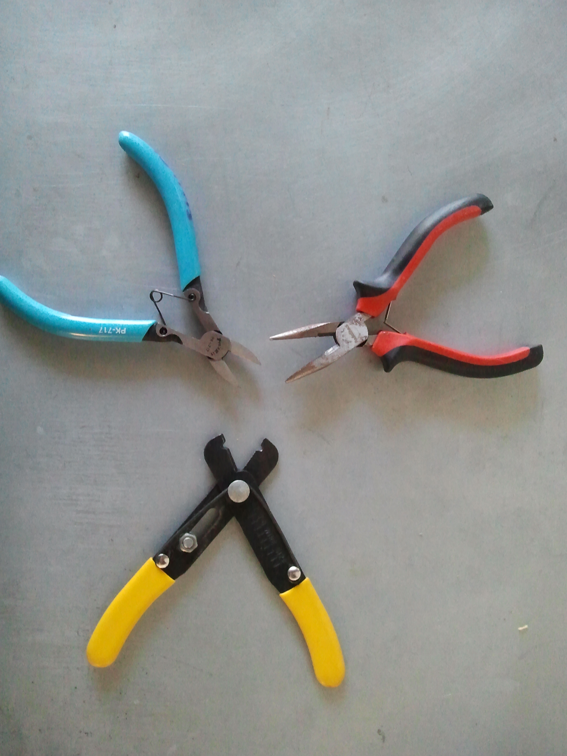
Most importantly, you want the wire cutters to have a small, fine tip, for cutting wires that are close to other wires:

That’s about it – it is useful to have other tools on hand but these are the only tools necessary

March 18, 2013 at 4:17 pm |
[…] is getting underway at the Bloomfield Science Museum. California artists and maker teacher team Teach Me to Make (Michael Shiloh and Judy Castro) traveled to Jerusalem as guests and Maker Faire emissaries and […]
March 18, 2013 at 8:09 pm |
[…] is getting underway at the Bloomfield Science Museum. California artists and maker teacher team Teach Me to Make (Michael Shiloh and Judy Castro) traveled to Jerusalem as guests and Maker Faire emissaries and […]
March 18, 2013 at 10:37 pm |
[…] of the things at the Maker Faire was CoffeeBots, small robots which use Arduino based electronics for easy modification and which were being […]
March 18, 2013 at 10:41 pm |
[…] of the things at the Maker Faire was CoffeeBots, small robots which use Arduino based electronics for easy modification and which were being […]
December 27, 2013 at 2:05 pm |
Augh! This line in the ultrasonic code is a problem. “// Distances of more than 2M or less than zero might be an error; ignore them
if ( (distance > 200) || (distance 100)”
It needs to be this way ….. if ((distance > 200) || (distance < 100))
Great fun!
December 27, 2013 at 5:10 pm |
Indeed true. Thanks for catching that! In fact, to agree with the comment, it should be if ((distance > 200) || (distance < 0))
If you built a Coffeebot please send pictures!
January 22, 2014 at 11:42 pm |
great work!
I’ve written a bluetooth activated version, you can check it out and use it freely if you like:
http://pastebin.com/gHuaqaPB
January 22, 2014 at 11:58 pm |
Awesome! Would love to see pictures or video.
January 23, 2014 at 1:50 am
How do I attach pictures within here?
January 23, 2014 at 2:03 am
I don’t think you can. Send us links and we’ll put them up: teachers AT teachmetomake DOT com.
June 3, 2014 at 12:28 am |
Hoping for help with Coffeebot – end-of-school year show/tell
Hello,
Thank you for the fun project! This is a great way of getting started in the world of Arduino and small robots.
I’m hoping that someone might be able to help me troubleshoot why our robot drives mostly in circles.
My 8 year old son designed a different deck for the robot and did much of the work himself, including some of the soldering. We finished the robot late last August in time for the school year; however, we never had much luck with getting the robot to run predictably (e.g. by steering it with a flashlight). He really wants to show his robot to his class, but it’s not behaving as we were hoping. Unfortunately, I lack programming and Arduino experience.
The robot seems to favor one side, it mostly runs in circles and it moves quite fast. If we hold the robot and shine a flashlight at the photo resistors, the running motor/wheel will switch sides.
Given the program in Maker Mag., do the Coffeebots typically drive in circles?
Do you have any programming suggestions that will make the robot more predictable? Ideally, we’d like to steer the robot with a flashlight.
Also, do you know if there is a way to stop or slow the robot down if the flashlight isn’t shining on the photo resistors?
Thank you for your help, I really appreciate it!
Kind regards,
KingKona
June 3, 2014 at 12:42 am |
Hello Jim,
I’ll be delighted to help.
First of all, I’m glad you told me that when you hold the robot and shine a flashlight at the photo resistors, the running motor/wheel will switch sides. This verifies that the photo resistors and motors are all working.
If the robot seems to favor one side, it sounds like one of the photo resistors is giving very different readings than the other. I can think of a number of possible causes and solutions, but let’s first verify that this is indeed what’s happening.
I like to use the Arduino built in examples for this, since we have high confidence that those programs are correct.
To test the photo resistors, open Arduino and go to File -> Examples -> Basics, and upload AnalogReadSerial. This program (sketch) will read from one sensor and send the result to your computer, where you can display it by opening the Serial Monitor, by clicking on the magnifying glass symbol near the top right of the Arduino program.
Before you upload, though, look in the program for this line:
int sensorValue = analogRead(A0);
and confirm that A0 is where you have connected one of your photo resistors. If you followed Judy’s build instructions, your sensors will be at A0 and A3, so leave can test the sensor attached to A0 without changing the program.
Upload the sketch, and don’t disconnect the USB cable. (You’ll need to hold the robot up so it doesn’t run away from you.) Now open the Serial Monitor (magnifying glass symbol) and after a second or two you should see a bunch of numbers scrolling by on the screen. I’d expect the numbers to be somewhere in the range of 200 to 900, very roughly.
These numbers represent the amount of light falling on the photo resistor, so if you cover up the photo resistor the numbers should decrease, and if your shine a light on the photo resistor the numbers should increase. I’d expect the numbers to vary over a range of roughly 300 to 600. Test this, and make a note of what happens.
Next you need to check the other sensor. Go back to the program and change A0 to A3 in this line:
int sensorValue = analogRead(A0);
Upload, open the Serial Monitor again, and again make a note of what happens to the numbers change when you change the light on the other sensor.
Tell me the results of that and we’ll go to the next step.
Regarding your other question, yes, you can certainly stop or slow the robot down if the flashlight isn’t shining on the photo resistors, by making changes to the program, but let’s first solve the first problem.
June 3, 2014 at 11:52 pm |
Hi Michael,
Thanks for the instructions. Here are the readings that I gathered under normal light conditions in my house:
–A0
>>standalone: 972
>>covered: 818
>>flashlight: 1021
–A2
>>standalone: 975
>>covered: 795
>>flashlight: 1022
The readings between A0 and A2 seem fairly close and consistent.
Please let me know you thoughts. Thanks for the help!
KingKona (Jim)
June 4, 2014 at 12:10 am |
Both sensors seem to be responding properly to light and dark, but I see that the values are very close to the top (maximum is 1023) and thus there isn’t much variation for different light levels. I can easily see how this could cause the behavior you describe.
I can think of two reasons for these values.
1) Please verify that the top (as viewed on the schematic) of the photo resistor is connected to 5V and not VIN. Too high a voltage would give you results like this, but would also damage the Arduino as it must never see more that 5V on its inputs. This is probably not what is going on but I want to rule it out to avoid damage.
2) More likely the resistors are too large in value for the particular photo resistor you have. Do you have any other resistors available? Try something between 10K and 100K ohms.
If you don’t have other values but do have more 150K ohm resistors, you can put one or two in parallel with the existing resistor which will create an equivalent resistance of 1/2 or 1/3 of the individual value. If you’re not sure what I mean, let me know and I’ll send a picture.
You can try this first on one side to see if it improves the range of numbers, and if it does, do the other side as well.
Let me know and we’ll go from there!
June 4, 2014 at 12:56 am
Thanks for the reply!
I verified that the power is in the 5v pin.
I’ll check to see if I have other photo resistors. If I have to purchase a few, would you recommend something closer to the upper end of 100K ohms?
Thank you!
June 4, 2014 at 1:14 am |
I mean to replace the fixed resistors, not the photo resistor.
June 5, 2014 at 12:03 am |
Hello Michael,
I think I know what you mean now, but a picture of the resistors would be very helpful. I don’t want to make a mistake.
Thank you!!
June 5, 2014 at 12:20 am
Here is a photo resistor attached to a fixed resistor. The photo resistor is on top.
Here I’ve added a second fixed resistor in parallel with the first resistor, to reduce the effective resistance:
June 6, 2014 at 12:12 am |
Hi Michael,
As I started to work on this I looked over the original resistors. It appears that the stripes are Brown/Green/White. If I have my resistor values correct, wouldn’t that be 15,000,000,000, not 150K ohms as noted in the directions.
Could that be the problem?
Is there a 1500M Ohm resistor just as small as 10K Ohm resistor??
If 1500M Ohm is right, then should I replace it altogether rather than solder one in parallel?
Thanks!
June 6, 2014 at 12:53 am
Indeed! You’ve used a 15,000M ohm resistor. That would completely explain your symptoms.
If all you have is 15,000M, you’d need a lot of them in parallel to bring it down to 150K.
However, if you have smaller values, you don’t need to remove the existing 15,000M resistors, if that’s easier. The effective resistance of resistors in parallel is always smaller than the smallest value, so if you put 150K in parallel with 1500M, the result with be less than 150K. In fact, since 15,000M is so much greater than 150K, it will have very little effect, and so the result will be very close to 150K. The exact number doesn’t matter very much at all.
Resistors physical dimensions are determined by their wattage, so as long as you get a resistor with the correct resistance in the same wattage (which is probably 1/4 or 1/8 watt) it will be the same physical size as your incorrect resistor.
June 6, 2014 at 1:39 am |
Michael,
Good grief. Apparently, I had mistaken yellow for white. (Yes, 15,000M ohm. I wrote 1,500, but meant 15,000). I will be using a multi-meter from now on rather than relying on color bands!
While shopping for resistors at my local electronics store, I noticed the Wattage-to-size difference (i.e. higher Wattage, larger resistor). The size doesn’t really vary based on resistance as long as you’re in the same wattage rating.
I think I’m going cut out that 15,000M Ohm resistor. I was only able to find 100K and 47K (1/4w) resistors. If I solder those in *series*, will 147K Ohm be close enough?
Thanks for all of your help!
June 6, 2014 at 2:19 am |
Don’t blame yourself. I’ve noticed that resistor manufacturers pay less attention to paint colors that are easy to distinguish: orange looks like red, red looks like brown, yellow looks like white.
Or maybe I’ve grown older 🙂
Yes, 100K and 47K in series will indeed make 147K, which is absolutely close enough. You may even get by with 100K alone. It doesn’t have to be terribly precise, as long as the values are not close to 1023 or 0 (as given by analogRead())
The goal is to get a good spread of values as you change the light level (dynamic range). You’ve already discovered that by choosing a resistor too far from the optimal value, your dynamic range is severely limited, resulting in a less reactive robot.
Good luck and please let us know how it goes! If you send a video or a link we’ll post it here.
June 8, 2014 at 4:02 am |
Hello again,
Well, it turns out that the original resistors were correct. After we cut them out and looked at the resistors in bright, natural light, the yellow stripe revealed itself.
The effort wasn’t a loss. My son enjoys soldering and was able to get more practice on his robot. However, my previous comment still stands–use a multi-meter and do not rely on color bands!
We learned a lot today. I believe that the problem has to do with the lower lighting in my house. Even with the new resistors, the robot simply drove in circles. Although, when I held the robot closely to a CFL light, both motors would run (albeit intermittently). For some reason, the robot would not respond to my flashlight (Maglite). So, we decided to take the robot out doors to test it in bright natural light.
Today was an oppressively bright day. Sure enough, the robot drove relatively straight, especially when it was facing a wall that reflected light evenly. I was able to steer the robot by placing my in front, or on the side, of a given photo resistor. Very cool!
I retested the photo resistors *indoors* according to your instructions and the readings were nearly the same. I will test the photo resistors outside tomorrow to see if there is a difference in brighter, natural light.
Unfortunately, my son will have to show his robot to his class in his classroom. His room lighting is fairly close to the lighting in our home.
Do you know if there is a way of making the robot more sensitive in lower light indoor conditions?
Ideally, we’d like to steer the robot with a flashlight.
Also, do you how we can slow the motors down so the robot doesn’t move so fast?
As always, thanks so much for your help! This has been a great learning experience for me and my kids.
June 8, 2014 at 6:01 pm |
Hi Jim,
Sorry there wasn’t an easy fix, and I’m sorry we didn’t get it working well enough for your son to show all the functionality in school.
I would still have tried lowering the value of the fixed resistor, either by replacing with a lower value or by placing another resistor in parallel. It’s been my experience that a useful range usually exists that is broad enough to work both indoors and outdoors. However here in San Francisco we don’t get a lot of super bright days to test this out, and your situation might be different.
If you can’t find a (fixed) resistor that gives you a suitable range both indoors and outdoors, you’d need two separate values, one for indoors, and one for outdoors.
I can imagine a way to have two different resistors in your circuit, connected to different digital outputs, and then using software to select which resistor is active. Setting the corresponding output to HIGH would enable that resistor, while setting the other output to an input would effectively disconnect the unused resistor. I can sketch this out for you if you wish, later.
Alternately you can simply duplicate the sensor circuit, same photo resistor but the different fixed resistor, and in software select one sensor for outdoors and one sensor for indoors.
I can also imagine (but haven’t tried) an automated way of the software figuring out which sensor seems to be working better, so you don’t have to reprogram it when moving from indoors to outdoors. The software could check both sensors and if one sensor isn’t changing much then use the other one.
Finally to your question about speed: Very simple. Instead of using the digitalWrite(motor, HIGH) which makes it run at full speed, use analogWrite(motor, 127). The number 127 is midrange: you can use any number from 0 (stop) to 255 (full speed). You can write the software (as you learn more) to change speed, for instance depending on how different the readings from the two sensors are, or just stay at a fixed value you like.
Good luck, and let us know how it goes!
June 8, 2014 at 6:13 pm
Hi Michael,
I like the ideas. Perhaps over the summer we can work on an indoor and outdoor setting.
However, initially, I will definitely try inserting another resister in parallel to see how the robot responds.
Trust me, even if my son doesn’t get to show the robot to his class, he’s in his glory by making these changes. The journey of experimentation outweighs the destination!
Thank you!! I will let you know how things go.
June 8, 2014 at 7:06 pm |
Your son has the true Maker spirit, and I’m proud to be an informational signpost on his journey of exploration.
June 9, 2014 at 6:45 pm |
Jim, I’ve been doing some research for another project and realize that I incorrectly calculated the value for the fixed resistor incorrectly. It should really be much lower than 150K ohm, perhaps as low as 10K ohm. I think in the past we’ve been lucky and have been operating in extremely dim situations, but I can see now that with even moderate lighting the value of 150K ohm is much too large.
Try reducing the resistor to 10K and let me know what happens. As I mentioned earlier, placing the 10K in parallel with the existing 150K is fine, if that’s easier.
I’m sorry I didn’t figure this out earlier, this would have saved you much time, and may have allowed your son to demonstrate control of the robot with a flashlight.
June 11, 2014 at 3:09 am |
Hi Michael,
Thanks for the update. It’s no problem, my son been enjoying this time. Once we get this going, he’ll have something to show his class in Sept.
We did add an additional (47K Ohm resistor) to the 147K Ohm resistors and it didn’t seem to make a difference. Then again, we tested it outside. Perhaps we should test it inside where there is less light?
We also replaced the photo resistors just in case, but it didn’t make a difference.
Given that the additional 47K Ohm resistor didn’t change the behavior of the robot, would you still replace the resistors with a 10K Ohm resistor? Or, would you go even lower?
Thank you!
June 11, 2014 at 4:14 pm |
Given the results of your experiment, I’d go lower. I’ve seen talk of a 1K resistor in bright sunlight for a similar photoresistor.
When you put in the 47K, did the readings shift down at all? The range of the readings will be your real indicator.
Another thing you can do: Measure the voltage between ground and the junction of the two resistors, where it connects to the Arduino analog input. If it’s close to 5V you need a lower fixed resistor. I’d aim for it to be around 2-3V for flashlight control.
In bright sunlight the flashlight won’t have much effect. Instead you can steer it with shade, e.g. a stick with a frisbee to shade the photo resistor.
Michael
June 17, 2014 at 3:43 am |
Hello Michael,
Here are the new readings after adding the additional resistors (see June 11 post above):
-A0
>>Standalone: 933
>>Covered: 867
>>Flashlight: 1016
-A1
>>Standalone: 936
>>Covered: 869
>>Flashlight: 1016
It seems that the readings are pretty close to my earlier readings before adding the additional resistors.
Regarding the voltages, here are the readings assuming I tested this correctly:
-A0 = 4.38v
-A2 = 4.34v
I tested the voltage with my red probe on the A0/A2 pins on the Arduino, and ground wire soldered to the power switch.
Thank you!!