Arduino ATtiny workshop
Project: Programmable Arduino Sound Device
Schematic:
Kit:
- 1 Attiny85 or ATtiny45
- 1 Speaker
- 1 Battery holder
- 1 3V Lithium coin cell battery
- 1 Photoresistor
- 1 22 K Ohm Resistor (red-red-orange) to go with photoresistor
Consumables:
wood, nails, wire, solder, etc.
Tools
hammer, wire cutters, wire strippers, needle nose pliers, soldering iron, etc.
Instructions for Builders:
Construction steps (pictures to follow):
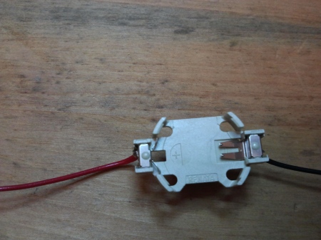
- Solder a red and a black wire to the battery holder. Make sure the red wire is attached to the terminal marked +
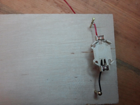
- Insert a pair of nails for the battery holder
- Attach battery holder to first pair of nails. Make sure the red wire is on top.
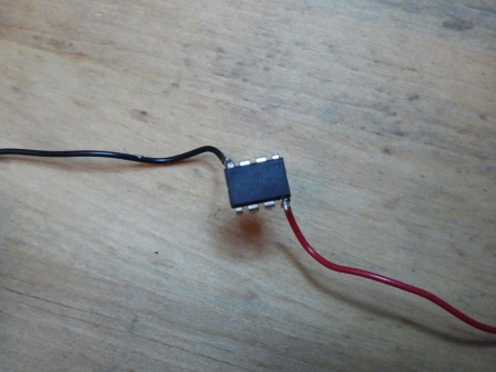
- Solder a red and a black wire to ATtiny. Make sure the red wire is attached to the pin (pin 8) opposite the dot (pin 1)

- Insert a new nail for the black wire of the ATtiny
- Attach the red wire of the ATtiny to same nail as the red wire of the battery holder. Attach the black wire of the ATtiny to the new black nail.

- Solder a blue and black wire to the loudspeaker. It doesn’t matter which is which.

- Attach the blue wire of the loudspeaker to pin 3 of the ATtiny, and attach the black wire to the same nail as the black wire from the ATtiny

- Insert two nails for the photoresistor

- Connect the photoresistor to the two new nails. The photoresistor is non-polarized, meaning it does not matter which way it is connected.

- Insert a new nail for the fixed resistor below the photoresistor
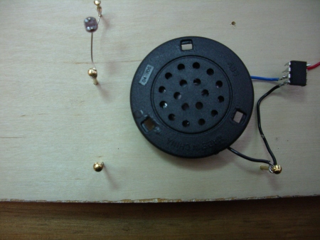
- Attach the fixed resistor between the photoresistor and the new nail

- Solder a blue wire between pin 2 of the ATtiny and the nail between the fixed resistor and the photoresistor


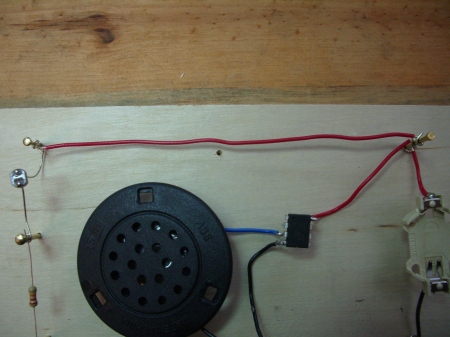
- Connect the two upper nails with a red wire
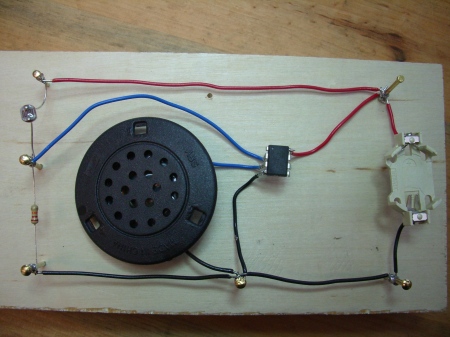
- Connect the three bottom nails with a black wire
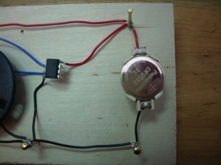
- Solder all connections to the nails
- Insert battery. Make sure the side marked “+” faces up
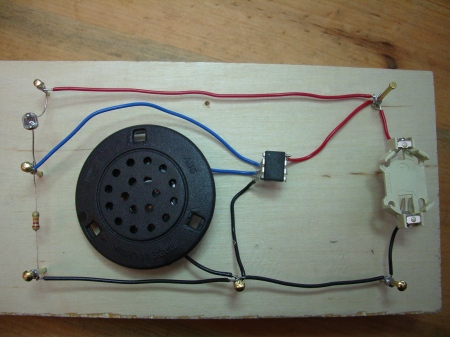
- If you have a pre-programmed ATtiny, proceed to step 19. If you have an unprogrammed ATtiny, follow the instructions (that I haven’t written yet) to program your ATtiny. You can also deduce these instructions from the links below. You will need something to use as a programmer, such as an Arduino, and a way to connect 4 wires to the ATtiny, such as tiny alligator clips or microhooks.
- Cover up the photoresistor with your hand and see if the sound changes

Instructions for Assistants:
Prepararations:
Preparation I: Installing ATtiny45 / ATtiny85 support in Arduino
- Download: attiny45_85.zip
- Locate your Arduino sketchbook folder (you can find its location in the preferences dialog in the Arduino software)
- Create a new sub-folder called “hardware” in the sketchbook folder.
- Copy the attiny45_85 folder from the attiny45_85.zip to the hardware folder.
- Restart the Arduino development environment.
Preparation II: Set up your Arduino as an ISP
- Download ArduinoISP revision 04 and unzip in the examples directory (E.G., arduino-0023/examples on Linux)
- Program Arduino with ArduinoISP
To Program ATtiny:
- REMOVE THE BATTERY FIRST!!
- Connect wires:
- ATtiny Pin 1 to Arduino Pin 10
- ATtiny Pin 5 to Arduino Pin 11
- ATtiny Pin 6 to Arduino Pin 12
- ATtiny Pin 7 to Arduino Pin 13
- ATtiny Pin 4 to Arduino Gnd
- ATtiny Pin 8 to Arduino VCC
- Select “ATtiny45 (w/ Arduino as ISP)” or “ATtiny85 (w/ Arduino as ISP)” from the Tools > Board menu
- Upload the sketch.
- You’ll probably get the following message, but don’t worry, the upload should have worked anyway:
avrdude: please define PAGEL and BS2 signals in the configuration file for part ATtiny85
avrdude: please define PAGEL and BS2 signals in the configuration file for part ATtiny85
References:
http://hlt.media.mit.edu/?p=1229
http://toasterbotics.blogspot.com/2011/08/programming-attiny85-arduino-style.html
http://jarv.org/2011/11/custom-musical-greeting-card-for-less-than-5/
http://hackaday.com/tag/attiny85/
Arduino Program (sketch)
// For the ATtiny workshop
//
// A3 is the light sensor
//
// PB4 is the speaker

// For a 20 MHz ATtiny85, delayMicroseconds can be between about 4000 (low frequency) and 1 (high frequency)
void setup()
{
  pinMode(PB4, OUTPUT);
}

// Simple tone
void loop()
{
  while(1)
  {
    digitalWrite(PB4, HIGH);
    delayMicroseconds(50);
    digitalWrite(PB4, LOW);
    delayMicroseconds(50);
  }
}

void setup()
{
  // PB3 and PB4 are unused during programming
  pinMode(PB4, OUTPUT);
}

// Raygun - like sounds
const int scale[]={3200, 1600, 800, 400, 200, 100, 50};

void loop()
{
  for( int i = 0; i < 7; i++)
  {
    digitalWrite(PB4, HIGH);
    delayMicroseconds(scale[i]);
    digitalWrite(PB4, LOW);
    delayMicroseconds(scale[i]);
  }
}

void setup()
{
  pinMode(PB4, OUTPUT);
}

// Theremin
void loop()
{
  digitalWrite(PB4, HIGH);
  delayMicroseconds(analogRead(3)/10);
  digitalWrite(PB4, LOW);
  delayMicroseconds(analogRead(3)/10);
}
Acknowledgements
Thanks to the authors of the pages listed in the references above
Thanks to my nephew Adam for helping me develop this project!

September 17, 2013 at 9:21 am |
I like the traditional breadboard you used. A few questions however, you have three sketches written there, can you use them at the same time, as it is there? or would you need to choose one to upload? If it doesn’t use it, does the ATtiny mind the extra code being there?
If anything I guess you do have some free pins so can have a push button to cycle through them.